Process History - Basic Steps to Apply a Filter with Blend Mode, Opacity, and Control Point Mask

The Process History window tracks each stretch, smooth, sharpen, deconvolution, and color adjustment filter that is applied to an image. Each filter applied to an image creates a filtered image layer that has its own blend mode, opacity, and mask specified on the Process History window. Blend mode and opacity of a filtered image layer define how the layer is blended with the previous image layer. A mask selects and blends different areas from the filtered image layer and previous image layer. Lighter mask areas select more of the current filter image layer while darker mask areas select more of the previous image layer.

A control point mask is a synthetic mask created by manipulating 16 control points to define where the mask is light and dark. First apply a filter to an image to enable Blend Mode, Opacity, and the Mask button on the Process History window. The default control point mask is an all white reveal all mask and is assigned when the filter is first applied to an image. Press the Mask button on Process History to display the Mask Surface window with the default all white reveal all control point mask already enabled. Left click on one of the red control points on the mask surface window and drag it up or down to make the mask lighter or darker. Hold Shift down and left click to move a red control point from side to side. Several preset control point mask can be selected and edited. Several control points can be moved as a group by selecting the points using the Mask Control Point Group list on the Mask Surface window. Right click on the control point mask to copy and paste the mask to any other filter or image.

Here are the basic steps for using a control point mask with any stretch, smooth, sharpen, decovolution, or color adjustment filter.


Step 1) Open the Image & Process History Window


First open the image using File | Open then use the Process History button on the top horizontal toolbar to open the Process History window. When an image is first opened Blend Mode, Opacity, and Mask are disabled on the Process History window since it takes two image layers to use these functions. The Read operation shown in the Operation list of Process History is the initial image layer. A filter is applied to create a second image layer and enable Blend Mode, Opacity, and Mask options. The mask along with blend mode and opacity define how the previous read layer is combined with the current filter layer to create the current image displayed. The default all white reveal all control point ask is automatically enabled the first time any filter is applied to an image.

Note the that the upper left and lower right corners of the image are too dark. A control point mask is ideal for controlling where a filter like Micro Curves is applied to increase the brightness of only the two dark corners.


Step 2) Apply a Filter to the Image to Enable Blend Mode, Opacity, and Control Point Mask


Apply any stretch, smooth, sharpen, deconvolution, or color adjustment filter to the intital image. In this case Stretch | Micro Curve is appiled to make the upper left and lower right corners brighter. The default normal blend mode, 100% opacity, and all white reveal all control point mask are assigned to the Micro Curve layer when Micro Curve is first applied to an image. Note that Micro Curve is added to the Operation list of the Process History window and is applied to all pixels of the image since the default all white reveal all control point mask with normal blend mode and 100% opacity are set. The Mask button is enabled on the Process History window and is used to display and modify the control point mask.

After a filter is applied to an image blend mode and opacity can be modified to blend the previous read image layer with the current Micro Curve filter layer. A mask is used to weight blending of the Micro Curve layer with the previous read layer pixel by pixel. Whiter mask areas weight Micro Curve pixels more than darker mask areas which weight the previous image layer pixels more.


After Micro Curve is applied to the image press the Mask button on the Process History window to display the Mask Surface window. The default all white reveal all control point mask is automatically enabled when Micro Curve or any other filter is first applied to an image. Since the control point mask is all white with normal blend mode and opacity 100% the Micro Curve layer completely replace the previous read image layer. As a result the corners are brighter but so is the entire image. The control point mask will be modified in step 3 so that only the dark upper left and lower right corners are made brighter by Micro Curve.


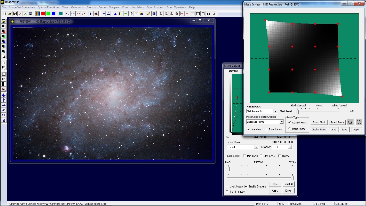
Step 3) Modify Control Point Mask, Blend Mode, Opacity, and Filter Parameters


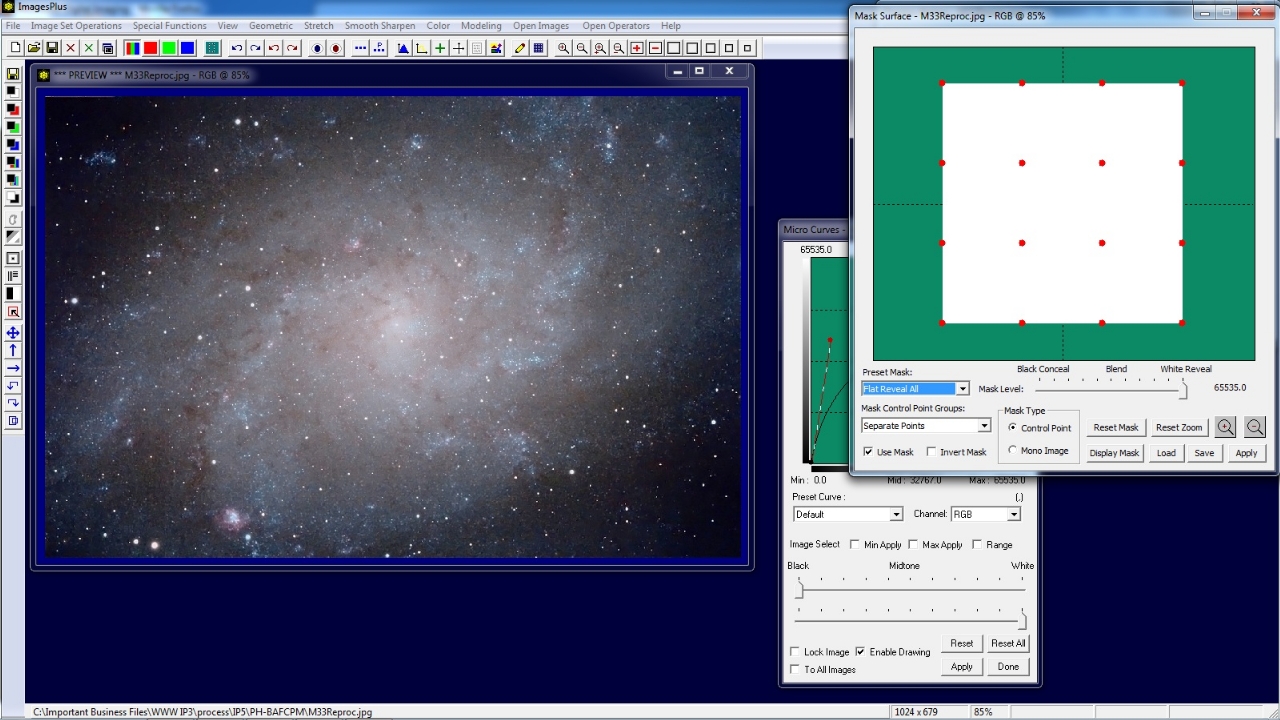
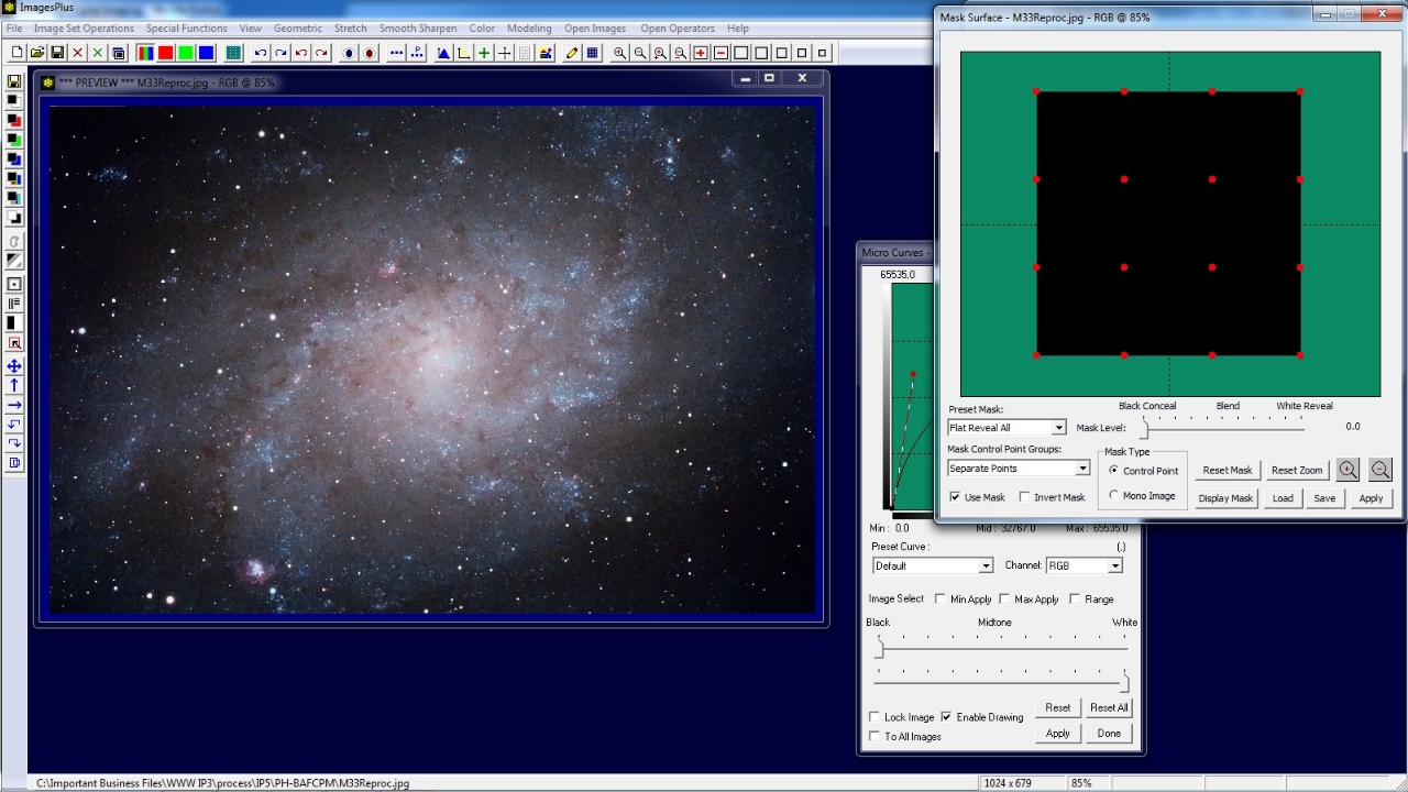
Move the Mask Level slider on the Mask Surface window all the way to the right to make an all black control point mask. Since the mask is all black the effect of Micro Curve is concealed and the previous image layer is shown. The all black control point mask will be modified in the next step so that only the bottom right corner of the image is made brighter by Micro Curve.


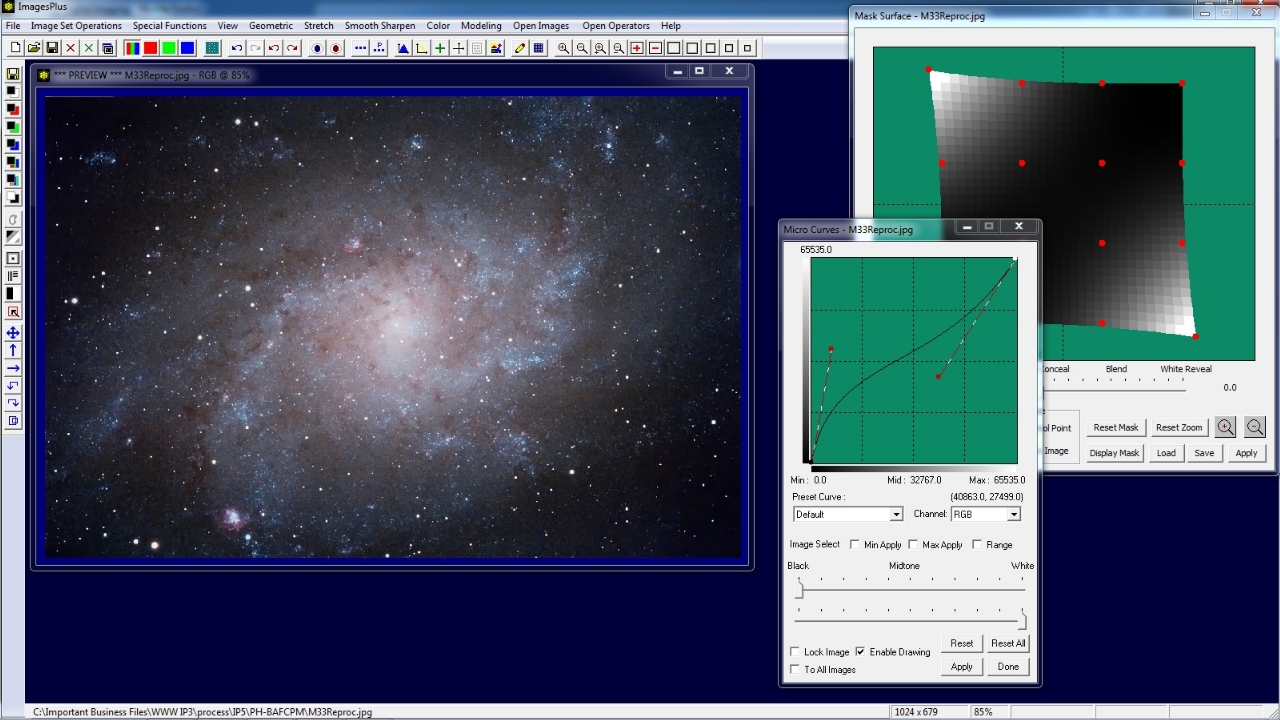
Left click on the bottom right red control point on the Mask Surface window and move the red control point so that the bottom right corner of the mask becomes lighter. Mask areas that are lighter select more of the Micro Curve layer so the bottom right corner of the image also becomes lighter.


Left click on the top left red control point on the Mask Surface window and move the red control point so that the top left corner of the mask becomes lighter. Mask areas that are lighter select more of the Micro Curve layer so the top left corner of the image also becomes lighter.


Adjust the control point mask, Micro Curve, and opacity on the Process History window to get the top left and lower right corners of the image to blend into the brighter parts of the image.


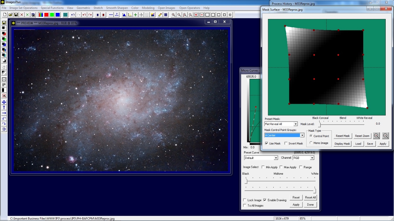
The red control points can be moved as a group. For example, select the 4 Center option in the Mask Control Point Group list. All of the edge control points turn dark red and are not active. Only the 4 center red control points are bright and active. Left click on any one of the 4 center red control points and move it up or down to adjust the center of the mask. In the example above the 4 center control points are moved as a group by pusing in on one of them to make the center area of the mask darker. The darker mask center allows no change to the image by the Micro Curve tool.


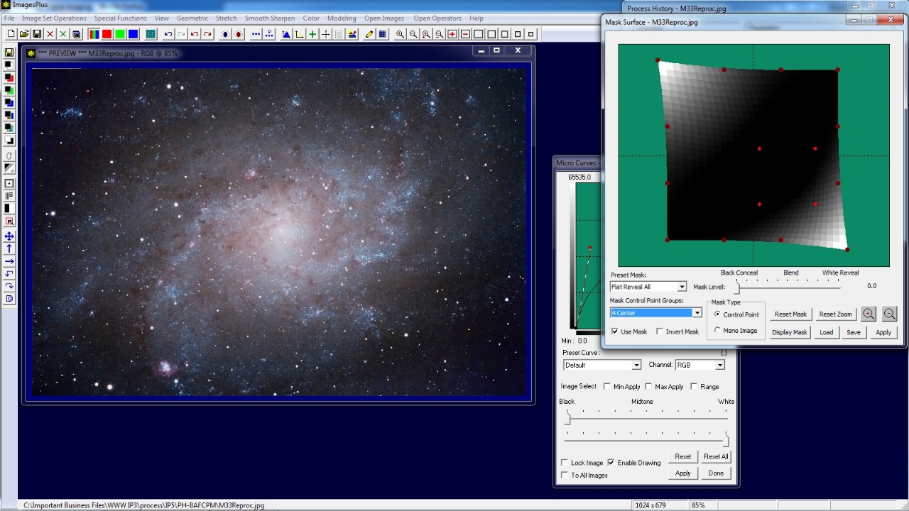
A single or group of red conttrol points can be move from side to side. Hold the Shift key down then left on a single or group of red control points to move from side to side. In the example above the 4 center control points are moved towards the bottom right as a group. Hold Shift then left click on one of the points to move the center dark region of the mask over M33.


Copyright © 2012 MLUnsold Digital Imaging. All Rights Reserved.